Veils
Mutable Instruments Veils 1
- Veils provides four vcas with an adjustable response curve.
Build notes
2020-12-31 8:00 PM
It seems like the Eurorack gods don't want me to have vcas.
Every time I decide to build a new module I forget that I need a VCA. Maybe it's because I find it boring? It's an essential part of a modular system but on paper it's such a simple device.
This time I finally remembered to plan a Veils build, but I recieved a blemished panel, which rubbed me in the wrong way. Coincidentally, good panels are out of stock and I will have to wait a few weeks / months to get a replacement. Many angry e-mails have been sent back and forth with the vendor.
I eventually calmed down and ordered the required components for the build. However I realized later on that the PCBs are a 0603 adaptation of Veils and I ordered 0402 components. Some kind of karma I guess.
This is not a huge problem though. I have a few options from here.
- Build it with 0402 components anyways
- Use this as an opportunity to learn how to order pcbs / fr4 panels from a pcb manufacturing service.
Both are viable options, but since Veils v2 hardware designs are released, I want to try ordering pcbs and panels for that instead of these. My original intention for building the v1 was to at least have VCAs in my system while I wait for v2.
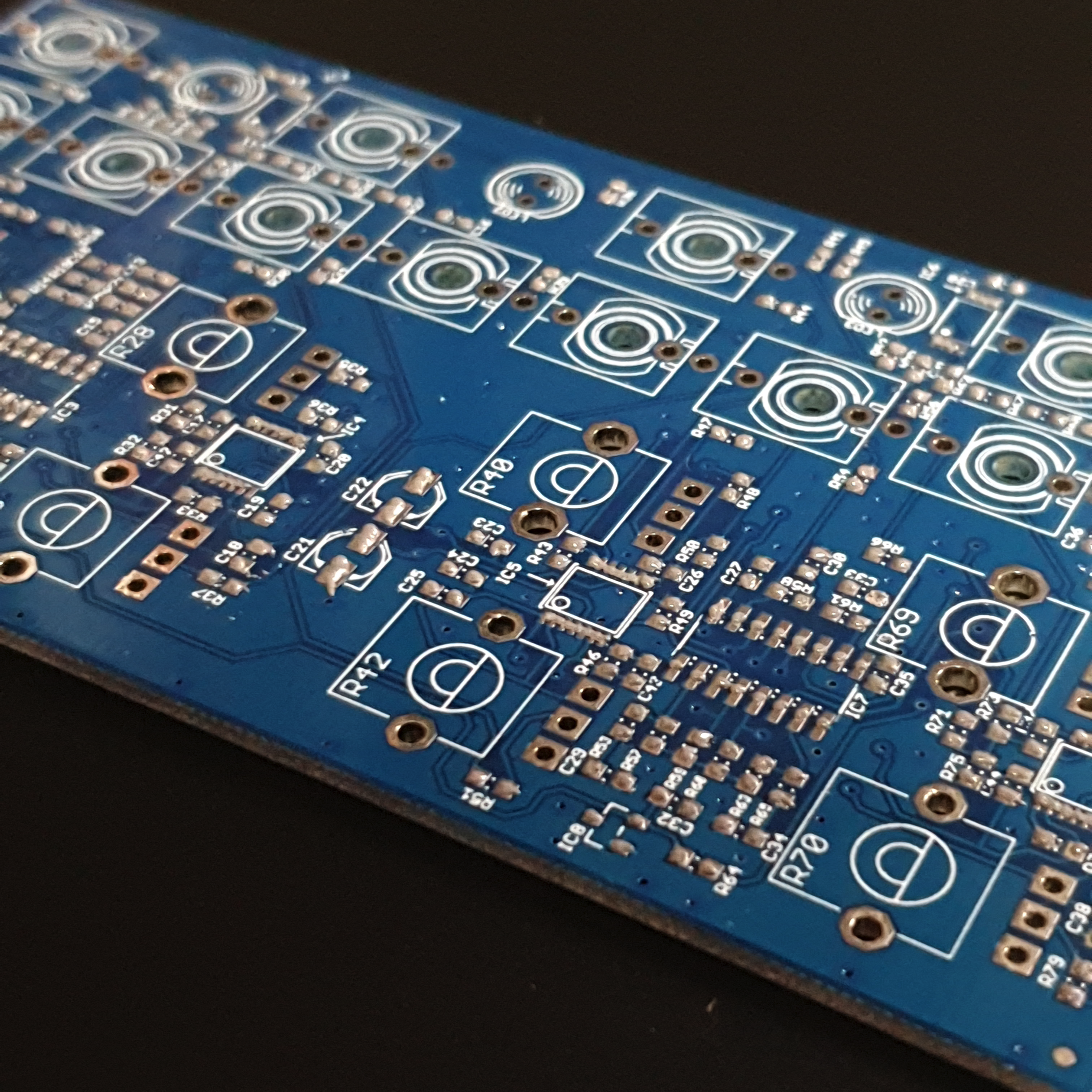
All components other than the 0402 packages seem to be identical. I just have to try to fit the 0402 packages between the pads spaced for 0603. This will be a bit tricky because I have to figure out how much solder paste I have to apply for each pad to compensate for the spacing difference. Luckily, I have two to build.
2020-12-31 8:43 PM
Shortly after I realized I ordered wrong packages for the build, I had to find something to control my frustration. The blemish panels for Veils was giving me bad vibes and I didn't want to look at them again.
So I grabbed a sanding disc and started peeling off the anodization and silk screen. After a few angry passes and then some with a finer grit, it looked pretty good. Not a perfect finish but miles better than looking at a b-stock panel.
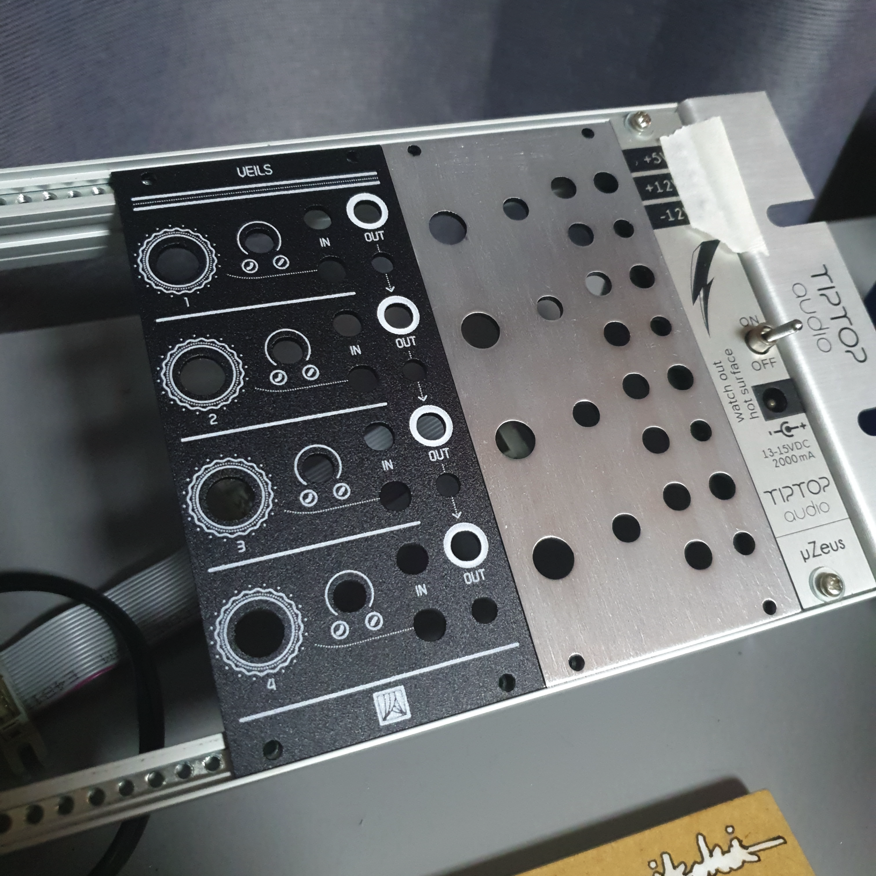 blemish panel vs sanded panel
The finish isn't perfect, but I like the gritty look of the raw panels. I could keep it as is or polish it more. Maybe sticker bomb it? It will be a good panel to experiment stuff on.
I should look into making my own panels
2021-01-06 11:15 PM
The components arrived. 0402 components are... way too small. I'll wait until the weekend to try building one of the veils.
Looks like the 0603 adapted pads have just enough space to fit a 0402 components between them, so it's definitely possible to use the original size.
I tried picking one of the resistors up with a tweezer and to my surprise, I think the static makes it stick to the tweezers. I guess they aren't ESD like they are advertized? I always clean them with IPA so it's not sticking onto the residual flux for sure.
2021-01-09 3:20 PM
- Started building.
- Sorted components by size.
- 0402 resistors
- 0402 capacitors
- the rest
2021-01-09 3:48 PM
Finished applying solder paste
2021-01-09 6:47 PM
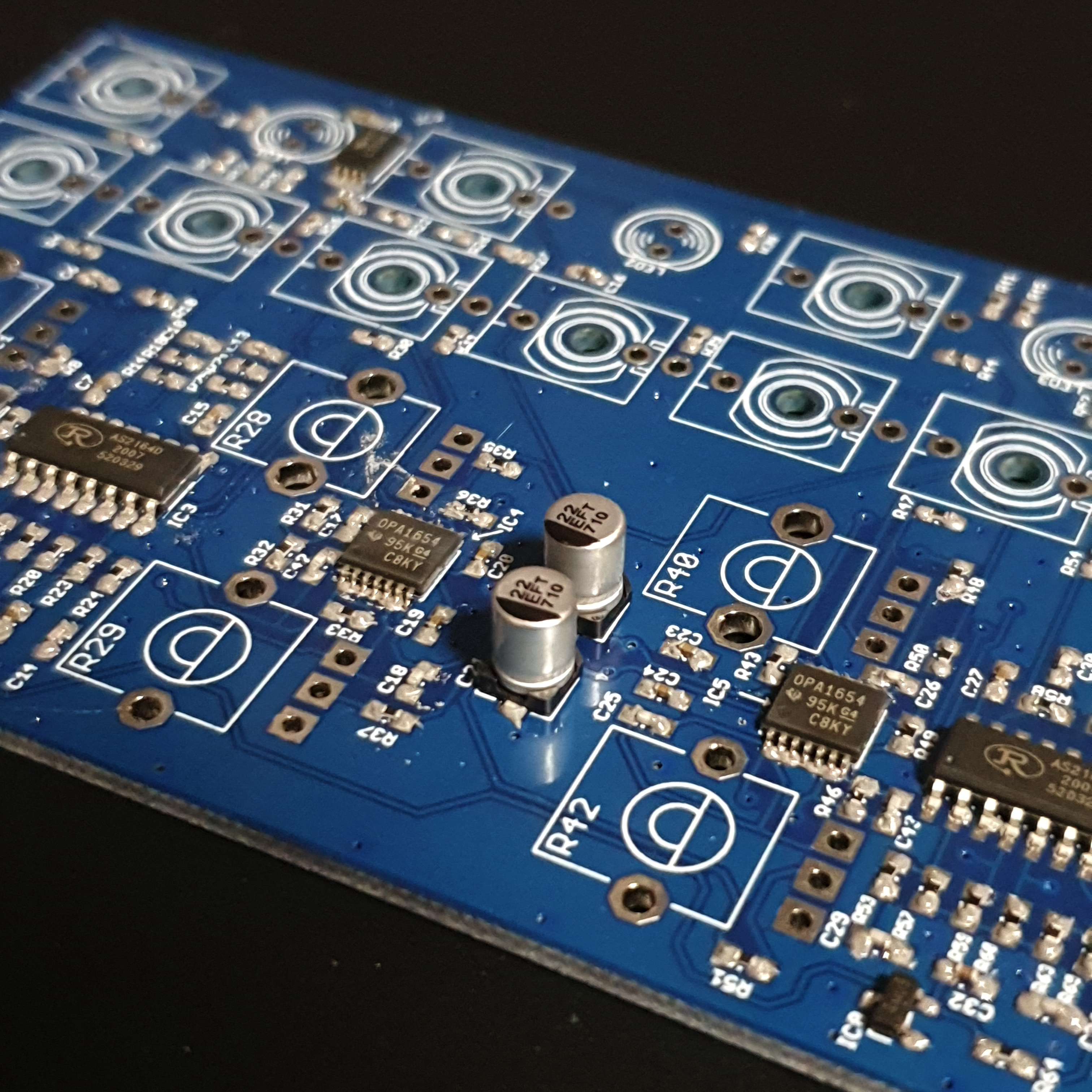
Components all placed
2021-01-09 7:06 PM
Flow on heat plate.
- preheat to 100C
- place pcb around 85C
- when 100C reached, crank up to 230C
- flow complete around 215C
- turn off heatplate, keep pcb on plate
- take pcb of plate
2021-01-09 7:16 PM
Inspection looking for bridges, inconsistent joints, and any shorts.
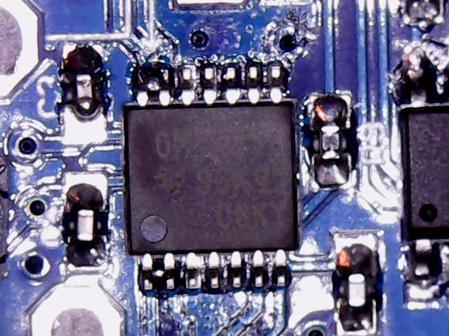 bridges on IC
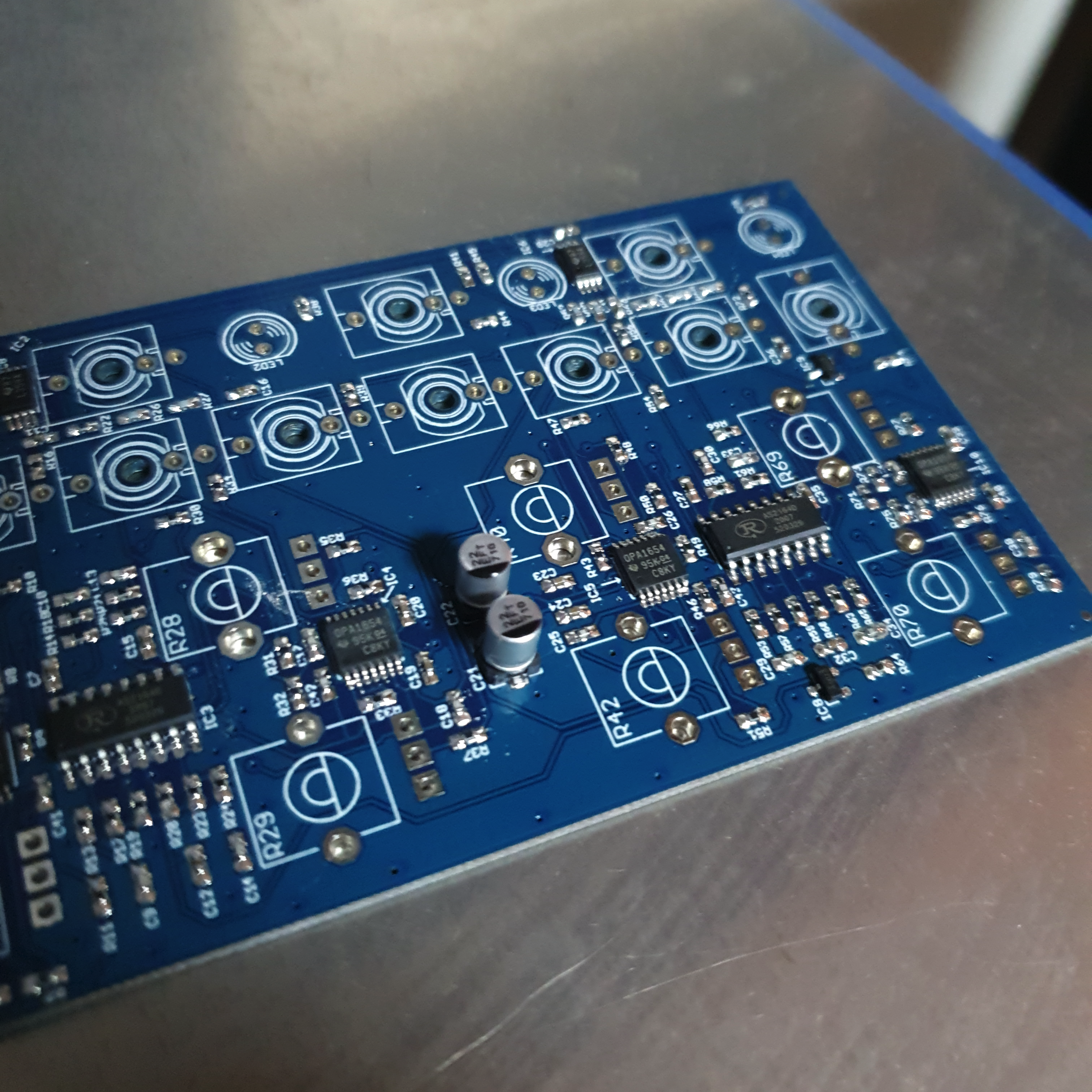
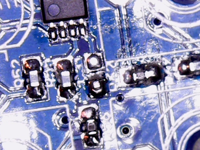 capacitor stands up and only soldered to one pad
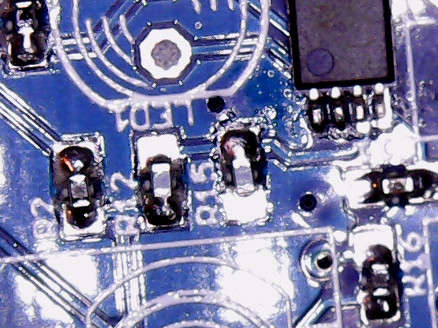 inconsistent solder amount of each pad
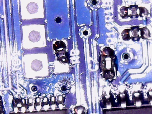 balled up joint and resistor trying to escape
2021-01-09 9:12 PM
- soldered all through-hole components after checking for shorts
- tested each channels individually for functionality before soldering. worked fine
2021-01-10 2:14 AM
-
Individual channels worked fine but daisy chaining was a bit wonky.
-
After hours of troubleshooting with a few friends, narrowed it down to a problem occuring between the cascade mixing of channel 2 and channel 3
-
As a result, channels 3 and 4's outputs were weaker and inverted.
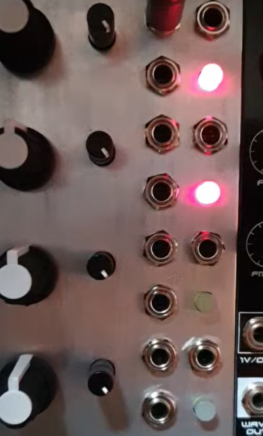 channel 2, 3, 4 output signal should be identical to channel 1's output signal, but channel 3 and 4's output are inverted and weak (dim and green)
 -
After many solder joint touch-ups, identified IC4's pins 8 and/or 9 were the culprit.
-
What was happening, was the 2 OPAMPs between channels 2 and 3 were inverting the signal twice while gain staging, and the second OPAMP had a faulty solder joint. which lead to the signal not inverting back, and also going through a nearby resistor which made it weak.
-
working as intended now
 finished module
Build debrief
Backlinks